


Blog
Blog
Chain feeding distribution system
29th August 2024 - News
Docked chain feeding systems consist of a closed loop with 90º curves, in which the chain is driven by a unit with a sprocket installed before the silo. The line begins and ends in the silo and drags the feed between the tacos, stirring the food less, maintaining the pellets and the homogeneity of the flour mixture more completely. These systems are best suited for installations with short lines and batch management per room since there are no problems in alternating the limit switches from room to room when filling and emptying them or changing the type of feed.
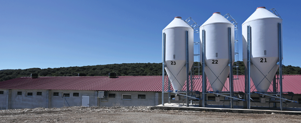
The cone of the silo
The function of the cone is to connect the silo with the extraction and allow its closure. They can be single (for one extraction) or double (for two).
The extraction
Extraction is the beginning and end of the closed circuit; the studded chain passes through them, loaded with feed. They are made of stainless steel and incorporate a feed-outflow control system. There are three types:
- Gravity filling: They have an adjustable scraper to adjust the flow. Some are for granules (simple and the size of spiral boxes) or flour (simple and double with a larger inlet). These extractors are unsuitable for systems where food is returned to the extractor since this is added to the one the extractor takes again, and the system could become saturated if it is very long.
- Self-propelled machined: They have a fixed internal spiral that moves with the passage of the chain and fills the line tube with a flow rate regulated by the diameter and pitch of the internal spiral (they fill 50% or 25% of the tube). They are simple and significant openings for granules and flour. These extractors have a system that discharges the line’s return at the beginning of the fixed spiral, allowing the return to be recirculated without overloading the line.
- Motorized machined: They have a fixed internal spiral operated by an independent motor that controls the flow with which the line is filled. They are simple and effective openings for granules and flour.
It is recommended that a section of transparent tube be installed at the extraction exit to check the filling percentage of the line tube.
Line tubes
Chain lines work in compression. When the chain passes between two curves, it tends to push against each other, creating much friction against the surface where it rests and runs. Metal tubes are ideal for their resistance and rigidity, but if the lines are correctly fastened and the tube thickness is adequate, PVC pipes can also be used. We work with Ø60 mm galvanized tube lines with a minimum coating of 20 microns of zinc with eight-bolt metal tube joints to ensure a safe and resistant joint.
Studded chain
The chain is made of specially reinforced steel with a breaking load greater than 3,200 kg and is tested metre by metre at 1,250 kg to guarantee its resistance and stretch it so that it does not do so once installed. The steel is tough to ensure minimal wear on the surface of the links with friction from use.
The chain studs can be Ø38 or Ø44 mm and are injected without plastic between the links. Thanks to this, the chain is much more malleable for installation; it barely stretches once installed and loads very little feed on the blocks, which is crucial in multiphase systems.
Along the route of the lines inside the warehouses, depending on the distribution of the pens, the drop-mouths with their respective downpipes (for filling ad libitum feeders) or dispensers (for animals with restricted feeding) are installed. As a linear distribution system, the feeders or dispensers are filled consecutively: first, second, third..., and so on until the end of the line. Inside the last hopper or dispenser, a sensor is installed so that the motor stops when it is complete, and after this, a capacitive safety sensor is installed on the line, which would stop the motor in case the sensor of the last feeder or dispenser does not.
Corners
It makes 90º turns on the line thanks to the internal pulley and allows ascending and descending sections. In 2001, Rotecna marked a milestone with the launch of our chain system, as it had the first corner with a clip system, which sped up the installation and maintenance of corners in front of which they closed with bolts. In turn, the curved spoke pulley, with the direction of rotation, allows the corner to self-clean while turning, considerably reducing friction inside the corner. The high-strength fibre polyamide pulley has a stainless-steel bearing for durability.
High-capacity traction machine
Other innovations we launched with our chain system more than twenty years ago were the drive wheel with independent synthetic teeth, a damping system, and a fuse on the axle. These innovations increase the installation’s safety in case of jams and lengthen the chain life by reducing tension and wear on the plastic studs.
In addition, the length of the tensioning pulley allows it to absorb more significant initial stress, which, combined with the option of a reducer with 20% fewer revolutions per minute, allows for more extended systems to be made than conventional systems. The pulley has a double-acting, interlocking pulley sensor, which protects the machine from overvoltage and chain loosening. It is also very accessible for easy inspection and maintenance. The finishes of the machine, the gear motor, and the internal chain tension system improve water-tightness and reduce the space needed for installation.
Power systems must be designed and sized according to each installation’s needs. Rotecna analyses each case and offers the best solution for optimal feed distribution inside farms, offering reliable, efficient, and safe systems.